User Tools
Table of Contents
1. iGrafx Modeling for Automation
This chapter is based solely on features for modeling processes to be Automated using the iGrafx Web-based client (or “Webclient”).
1.1 Creating a new model
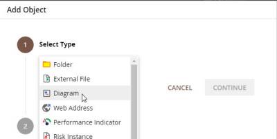
1. Click on “Add object” (or right-click a folder and choose “Add Child Object”).
2. Choose “Diagram”.
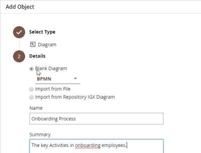
3. Choose ‘Blank Diagram’, ensure the type is BPMN (only BPMN diagrams may be deployed to automation), give the object a name (and optionally a summary), and click on “FINISH”.
You will then have created a web diagram, and be placed in editing mode on your diagram.
1.2 Model processes
The modeling options in iGrafx Process Automation (a.k.a. iPA or TIM) will be covered simply and clearly by using the following process example shown below. This example is an onboarding or recruitment process. After the process starts, tasks like “create personnel file” take place. Followed by that are the parallel tasks “organize workplace” and “create network account”. Whether hardware is required, is an “either-or decision”, so the process can only run through one of the two possible drawn paths from an Exclusive (OR) Gateway. If hardware is required, the new employee is notified with an automatic email and the process ends after being automatically archived (a.k.a. ‘archivation’ is performed on the running process instance).
Drawing the iGrafx Diagram
This ‘Quick Start’ guide assumes you are familiar with drawing diagrams using your web browser. If you need a refresher, see the iGrafx Web Diagramming Tutorial
The following shows a couple of pictures, reminding you that you can drag-drop Pools (containers for shapes), click the green “+” icon to create Lanes (Swimlanes® in the Pool), and even drag-drop shapes into the Lanes (or Pool).
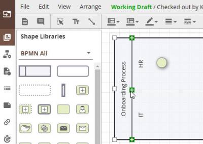
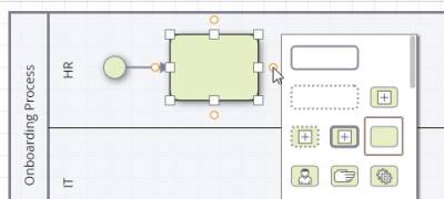
Also that you can click the orange dot on the shape to place another shape (e.g. to the right of the placed shape).
Please create the following diagram:

We will now highlight some key features of the process diagram, and its relevance to automation.
Parallel Gateway (AND link)
Parallel Gateways indicate the start or end of parallel flow, are denoted with a “+” in the Gateway diamond shape, and creates an ‘AND’ behavior. When using a Parallel Gateway with a number of tasks, all tasks have to be finished before the AND Gateway is satisfied and the next activity is started. Therefore the activities to be performed in parallel have to be between two Parallel Gateways performing ‘AND’ functions. These have to be connected with transitions like shown above.
Exclusive Gateway (Decision, XOR)
Exclusive Gateways indicate the start (or end) of either-or ‘exclusive’ paths being taken, are denoted with an “X” in the Gateway diamond shape, and create an ‘OR’ (or XOR) behavior. Lines are drawn, and automatically labeled, from the Exclusive Gateway to the activities that are up for selection (one OR the other). In automation, if no ‘Smartform’ prompts the user to enter a decision, the user will get to choose via an automatically generated popup prompt which way to go.
1.3 iPA attributes
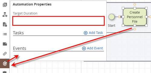
For every activity, tasks can be described, and events (that trigger an ‘actionhandler’) can be added by selecting the shape, and then clicking on the automation button on the diagramming toolbar on the left side of the diagramming space.
Attributes
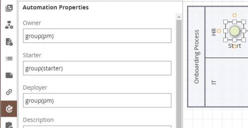
The following table gives an overview of some of the key attributes you can enter in fields for an Activity or the Start shape.
| Attribute on activity | Description |
|---|---|
| Duration | Input and maintenance of durations. Please note: The two last positions are minutes, and follow hours. Example: 30 min = 30; 1h = 60 or 100; 8h = 800; 1 week = 4000 (5x 8h) |
| Tasks | Via add tasks you can add a number of tasks |
| Events | Here actions can be defined that trigger an actionhandler during runtime. |
| Starter* | Here a user or a group must be specified, which is allowed to start a process in iPA. Example: user(max.mustermann) or group(starter) |
| Owner* | Here a user or a group must be specified, which later is allowed to own a process in iPA. Example: user(max.mustermann) or group(pm) |
| Deployer* | Here a user or a group must be specified, which later is allowed to deploy a process in iPA. Example: user(max.mustermann) or group(pm) |
| Smartform (Not Shown) | Here the XHTML code defining a ‘Smartform’ is put in. The Smartform allows an the designer of the automation to have full control over the prompts at each Activity of the process, to help ensure correct and complete information is entered. |
| Section Definition (Not Shown) | Here the XML code defining permissions for each ‘Section’ (or step) of the process can be entered, controlling which users can read and/or write information when performing the process. |
* Note that ‘starred’ fields are required (specifying the Starter, Owner, and Deployer of a process is required for deploying and running a process).
1.4 Deployment Check and Deployment
Deployment Check
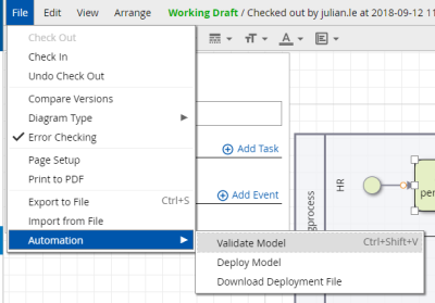
Before deploying a process it is recommended to conduct a so called “Deployment Check”. The editor automatically checks whether the process is publishable and executable. To conduct a Deployment Check click on File > Automation > Validate Model (or simply press Ctrl+Shift+V):
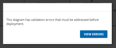
An output window will show, either informing you there are no errors, or listing the specific errors that validation found.
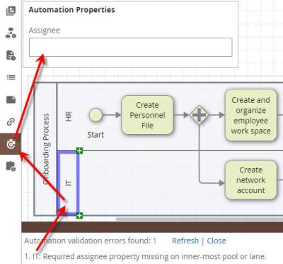
For example, if you forgot to put the ‘group’ that is assigned to perform tasks in the “IT” Lane, you might get a window like the following, and you could click the Automation Properties button to enter the correct group (e.g. “group(pm)”):
Deployment
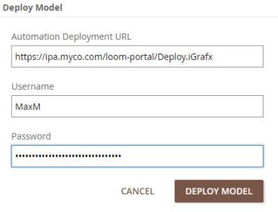
The publishing (Deployment) of the process to the iPA environment Can be accomplished by choosing File > Automation > Deploy Model.
The URL to deploy to is your automation server, followed by “/loom-portal/Deploy.iGrafx”. After putting in your username and password, the process is deployed by clicking on “Deploy Model”.
1.5 Special characters
When modeling with iGrafx it should be noted that no special characters (ß, §, $; #, „“, *, {, }) can be used in the process model and task description.
Login
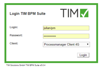
1. Put in username and password.
2. Choose Processmanager-Client or Processmanager-Client 4G.
3. Confirm login.
2.1 Automation Clients to Start and View Processes
Processmanager-Client 4G
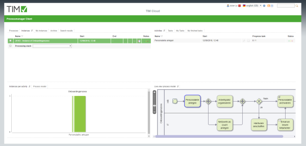
The Processsmanager-Client 4G is divided into 4 areas:
- In the top left you can find the tabs “Definitions” (all process definitions that you can start), “Instances” (the started instances of a definition), “Archived instances”, and “Search results”
- In the top right you can find the tabs “Activities” (the activities of the selected instance), “My tasks” (all of the logged in user's tasks) and “My finished tasks” (all already finished tasks)
- In the bottom left you can find the tab “Instances per activity” graph, where which tasks a started instance is on. In the tab “Processdefinition” the process model is displayed
- In the bottom right you can find a graph of the process model and what Activity is ‘active’ in the tab “process instance”
Processmanager-Client 2G
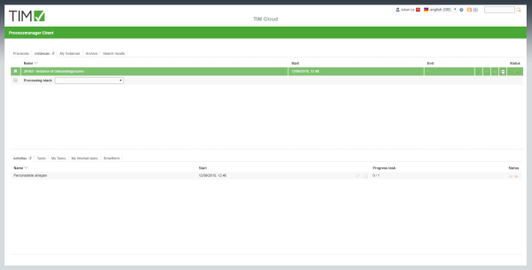
The Processmanager-Client 2G is built like the Processmanger-Client 4G. The only difference is that no graphs are shown.
3. Definition and Instances
A Definition can be seen as a template for a number of instances.
3.1 Functions of the definition
Context menu
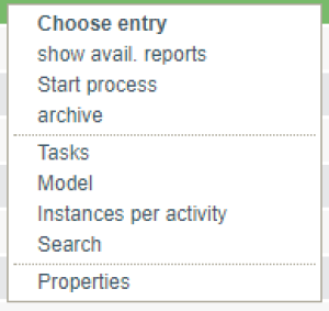
You can find the following points in the Context menu:
- Choose entry
- Show avail. reports (Download of reports)
- Start process (starting a new instance)
- Archive (archives the definition - only works, when no running instances are left)
- Tasks (displaying the definition's tasks)
- Model (displaying the process model)
- Instances per activity (Graph showing activities where single instances are located)
- Search (Searches single instances in the basis of smartform inputs)
- Properties (Opens the properties window)
start Instance
1. First you must choose a defintion

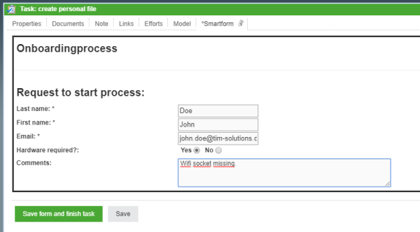
2. By clicking on the + symbol or in the definition's Context menu the following popup appears:

3. Fill the fields in the tab “properties” and in the smartform. Attention: Mind the required field in the smartform (marked with *). If these are not filled in, the instance can not be started.
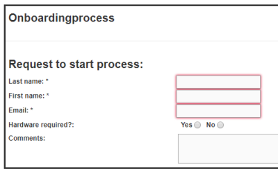
4. By clicking on “Start process” a new instance is started.
3.2 Instance's functions
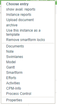
Context menu
You can find the following options in the Context menu:
- Choose entry
- Show avail. reports (Download of reports)
- Instance Reports
- Upload Document
- Archive (archiving the instance, it will then be moved from the tab “instances” to “archived instances”)
- Use this instance as a template (opens the popup “start instance” and fills the smartform with values from the to be copied instance)
- Remove smartform locks
- Documents (management and upload)
- Note (add and read)
- Swimlanes (table with all swimlanes as well as users and groups)
- Model (This function shows the graphic process model)
- Gantt (This function shows an overview, how many instances are on which activity.)
- Smartform (Displaying and editing smartform)
- Efforts
- Activities (List of all activities with earliest/latest start and end time, as well as milestones)
- CPM-Info (planned start, planned end and buffer)
- Process control
Properties
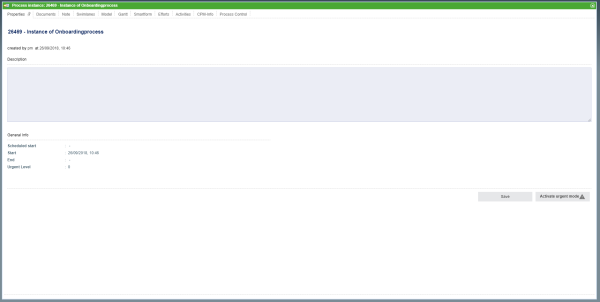
Name, starter, description, process start and end can be found in the properties window of the instance.
Moreover you can reach documents, note, swimlane, graph, gantt, smartform, activities, and CPM-Info. (Description see Context menu)
4. Activities and Tasks
By clicking on an activity the subordinate tasks are shown.
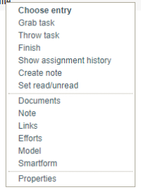
4.1 Context menu
You can find the following options in the Context menu:
- Choose entry
- Grab task (you will be assigned to process this task)
- Throw task (You will be deregistered as the processor and the task will be moved back to the group)
- Finish
- Show assignment history (all assignments of this task are recorded)
- Create note
- Set read/unread
- Document
- Note
- Links
- Efforts
- Model
- Smartform
- Properties
4.2 Properties
Via the Context menu you can get to the properties of the single task.
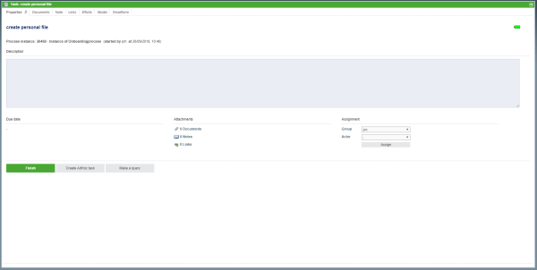
Here you can find:
- The task's information (like e.g. name, instance, starter)
- The remaining time (bar in the top right)
- The description put in the definition
- Due Date
- Number of attachments (documents, notes and links)
- Assignment (Here other groups or users can be selected and assigned.
- “Finish task” button
More tabs, in which you can manage and upload documents, maintain notes, call links, register efforts as well as reach the graph and smartform.
4.3 Finish task
Tasks can be marked finished in three different ways:
1. Via Context menu
2. Via properties view
3. By clicking on the checkbox at the end of the table
You then have to confirm that the task is really marked as finished:

If you have already finished more than one task, by using the Ctrl key, you can select a number of tasks by clicking on the checkboxes (selected tasks are green).
Then click on one of the checkboxes of a selected task and the popup will appear.

