
User Tools
Table of Contents
1. Creating and editing process models
The iGrafx Platform (diagramming with your web browser) is necessary in order to model processes with iGrafx and to deploy (i.e. publish) them in iGrafx Process Automation (iPA), also known as TIM. If there are any questions pertaining to the topic of available licenses, please refer your question to your administrator.
This section explains the basic functions for working with process models.
1.1 Logging into the iGrafx Platform
You may have one or more repositories defined for use in the iGrafx® Platform. Your System Administrator will have enabled which repositories are available to you. In order to use a repository, you must first connect to it. Your administrator should provide you with the following information necessary to connect to the established repository that will be used:
- iGrafx® Platform URL
- Username and Password (if needed; you may be automatically logged in instead)

To that end, follow the steps below to connect / log in to the repository:
- In the Address bar of your browser enter the appropriate URL and press Enter. If you are not automatically logged in through ‘Single Sign-On’ (SSO), then going to the URL will display the iGrafx® Platform login screen:
- For Username, enter the provided Username (case sensitive)
- For Password, enter the provided Password (case sensitive)
- Click on the
 button.

Once you log in to the iGrafx® Platform, you can access the content of any repository (that you’ve been given permission to access) via its repository tree. To access a repository tree, do the following:
- Click the
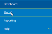
 icon on the upper left-hand side of the Platform Navigation pane to display the menu and then select the “Model” option:
Note: Clicking the icon (right above the menu) will hide the Platform Navigation menu, giving you more real estate space on your screen for viewing other items, such as diagrams.
- Upon clicking the “Model” option, the last iGrafx® repository that you navigated to should display in the form of a repository tree (as shown below). It is also possible that if you’ve been given permission to access only one repository in the iGrafx® Platform, then the tree of that repository should display automatically.
The screenshot below shows an example of a repository tree for a repository called “Training”.
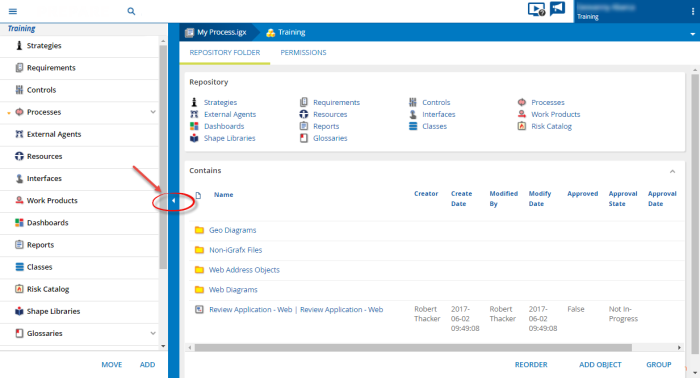
You may choose to hide the repository tree to give you more room in your screen when viewing items such as process diagrams. To hide the tree, click the bar that is called out by the arrow in the screenshot above. To make the tree visible again, click the bar on the left hand side of the screen (when visible).


1.2 Creating a new model
- Right-click on a folder where you want to add a diagram, and chose “Add Child Object”.
- Choose Diagram.

- Choose ‘Blank Diagram’, ensure the type is BPMN (only BPMN diagrams may be deployed to automation), give the object a name (and optionally a summary), and click on “FINISH”.

You will then have created a web diagram, and be placed in editing mode on your diagram.


1.3 Editing process models
The modeling options in iGrafx Process Automation will be covered by using the onboarding process example shown below. After the process starts, tasks like “create personnel file” take place. Followed by that are the parallel tasks “organize workplace” and “create network account”. Whether hardware is required, is an “either-or decision”, so the process can only run through one of the two possible drawn paths from an Exclusive (OR) Gateway. If hardware is required, the new employee is notified with an automatic email and the process ends after being automatically archived (a.k.a. ‘archivation’ is performed on the running process instance).
Drawing the iGrafx Diagram
This ‘Quick Start’ guide assumes you are familiar with drawing diagrams using your web browser. For more information, see iGrafx Web Diagramming Tutorial
Please create the following diagram:

The following pictures illustrate that you can drag-drop Pools (containers for shapes), click the green “+” icon to create Lanes (Swimlanes® in the Pool), and even drag-drop shapes into the Lanes (or Pool):

Remember also that you can click the orange dot on the shape to place another shape (e.g. to the right of the placed shape):

We will now highlight some key features of the process diagram for its relevance to automation.
1.4 iPA Attributes / Properties
Elementary attributes which determine the functionality of each element (step or shape) of the process may be assigned. These attributes are called iPA Properties.
The following properties focus on using iPA.
Setting values for attributes by using the Attribute Editor
Elements within a diagram often entail many editable attributes. Some of these have an influence on visual representation (e.g. the exact type of loop for specific BPMN tasks), while others do not have any visual influence.
To enter iPA Properties in a shape (e.g. Activity), select it and ensure the Automation Properties button on the toolbar is selected:

The ‘Start’ shape has different Automation Properties, as it controls behavior such as which user(s) may deploy the process to automation, start a process instance, etc. It also defines the ‘Smartform’ to gather user information (if any), and Section Handling. This is explained in more detail below.
iPA Attribute
The iPA specifications provide access to certain attributes via the Automation Properties window. Only some of these attributes also have visual effects. The following table provides an overview of these attributes.
Attributes of a starting element

Certain attributes of the starting element of a process need special attention to ensure that a process model will be properly executed by iPA.
Owner MANDATORYFIELD = A user or a group must be entered in this field. This gives the designated user or group the right to own the process in iPA at a later point in time. Multiple groups or users can be added and are separated with a semicolon: “user(a);group(b)” For example: user(john.doe) or group(owner) or all()
Starter MANDATORYFIELD = A user or a group must be entered in this field in order to be eligible to start instances of the process in iPA at a later point in time. Multiple groups or users can be added and are separated with a semicolon: “user(a);group(b)” For example: user(john.doe) or group(starter) or all()
Deployer MANDATORYFIELD = A user or a group must be entered in this field in order to be entitled to deploy the process in iPA. Multiple groups or users can be added and are separated with a semicolon: “user(a);group(b)” For example: user(john.doe) or group(deployer) or all()
Description = Here, a description of the process is entered. This will be shown in iPA.
Smartform = The definition of the Smartform should be inserted here. A ‘Smartform’ is HTML5 (XHTML) code to define a form to gather user data or interact with the user.
Section Definition = The definition of the section handling should be inserted here. Section Handling helps control what permissions users have, e.g. read or write access.
Escalation Handler = An Action Handler can be inserted in this field.
Count critical = This option should be selected if the CPM is to be calculated while automating this process.
Entering Attributes of an Activity
Attributes have to be entered in order to ensure that activities are properly executed in iPA.
Target Duration = Entries and management of durations. Information on notation: The last two digits represent minutes followed by hours. For example:
30 min = 30
1 h = 60 or 100
8 h = 800
1 Week = 4000 , if 8 hours per day is entered into the calendar profile.
Tasks
An Activity can have zero or more Tasks. The task can be assigned to specific roles or people, and can contain links to other information or pages. A user can mark a Task as done, and only when all Tasks are done can the Activity be completed. Click the ‘Add Task’ button to add a Task.
Name MANDATORYFIELD = Name of the task. No special characters are allowed to be used in this field.
Role Assignment = The role of the executing employee is defined here.
Description = A concise description of the task can be provided here.
Links = You may create links to other content. You may have a simple URL, or have a parameterized Link to content.
A more detailed description on the topic of tasks is provided in Tasks.
Events
An Activity can have zero or more Events. An Event can be used to call an actionhandler, e.g. to ensure a Mandatory field of a Smartform has been supplied. Click the ‘Add Event’ button to add an Event.
Name MANDATORYFIELD = Name of the event. No special characters are allowed to be used in this field.
Event Type = When the Event is executed, either on entry to or leaving the Activity, is defined here.
EventClass MANDATORYFIELD = The Action Handler to call. Autocomplete will help you type the correct syntax for the actionhandler to use.
Mandatory Fields = Any Mandatory fields, e.g. when using the MandatoryHandler, can be provided here.
Parameter = Any parameters, e.g. the ‘condition’ for the ConditionalMandatoryHandler, can be provided here.
Final state (End Event)
The 'End Complete Process' property can be set on an BPMN End Event (Final state). If set, this will cause the instance to be terminated. This would normally be set on a BPMN Terminate Event and if executed would terminate all parallel paths of this instance.
Managing attributes in Pools and Swimlanes
Attributes also have to be managed properly on Lanes to ensure a smooth process. The Lane indicates the assignee;the individual employee or the group responsible for executing the tasks of this lane. To enter the assignee, click the Lane, click the Automation Properties button (if not already selected), and enter a group or user:

2. AND, XOR and OR
Parallel Gateway (AND link)
Parallel Gateways indicate the start or end of parallel flow, are denoted with a “+” in the Gateway diamond shape, and creates an ‘AND’ behavior. When using a Parallel Gateway with a number of tasks, all tasks have to be finished before the AND Gateway is satisfied and the next activity is started. Therefore the activities to be performed in parallel have to be between two Parallel Gateways performing ‘AND’ functions. These have to be connected with transitions like shown above.
Exclusive Gateway (Decision, XOR)
Exclusive Gateways indicate the start (or end) of either-or ‘exclusive’ paths being taken, are denoted with an “X” in the Gateway diamond shape, and create an ‘OR’ (or XOR) behavior. Lines are drawn, and automatically labeled, from the Exclusive Gateway to the activities that are up for selection (one OR the other). In automation, if no ‘Smartform’ prompts the user to enter a decision, the user will get to choose via an automatically generated popup prompt which way to go.
3. Endings
Completely Terminating Ending
If you use a “Completely Terminating Ending” (Terminate Event in the Shape Library), it will upon arrving at that ending terminate the whole process. Be sure to set 'End Complete Process'on the Automation properties page as described above.
![]()
Partially Terminating Ending
A “Partially Terminating Ending” can be used in the model by inserting a Generic Event and the drawing an arrow from an Activity to it.
Once you arrive at a “Small Ending” it will not terminate the whole event, but rather just one way. This way you can terminate one “Way” of an AND Gateway, but the process will still continue.

4. Mail nodes
The mail node is an easy-to-use functionality, which allows the user to send standardized e-mails with iPA. These e-mails may entail messages to contact external individuals and groups as well as participants of the process and relevant decision makers. The e-mails may contain information on the process itself or reminders to execute tasks in iPA. See the mailnode help for more information.

5. Deployment and links
Real-Time Checking
The BPMN diagram type conducts specialized real-time error checks. These are meant to ensure that every chart meets the specifications of the BPMN-standard. This procedure in turn helps guarantee that each diagram is exportable and executable with iPA. These kind of real-time error checks are automatically done during the modeling stage.
Deployment Check
Before deploying a process it is recommended to conduct a so called “Deployment Check”. The editor automatically checks whether the process is publishable and executable. To conduct a Deployment Check click on File > Automation > Validate Model (or simply press Ctrl+Shift+V):

An output window will show, either informing you there are no errors, or listing the specific errors that validation found. For example, if you forgot to put the ‘group’ that is assigned to perform tasks in the “IT” Lane, you might get a window like the following, and you could click the Automation Properties button to enter the correct group (e.g. group(pm) ):

Deployment
The publishing (Deployment) of the process to the iPA environment Can be accomplished by choosing File > Automation > Deploy Model.

The URL to deploy to is your automation server, followed by “/loom-portal/Deploy.iGrafx”. After putting in your username and password, the process is deployed by clicking on “Deploy Model”.
6. Subprocess
Main process and subprocess
Processes may have hierarchical structures. Because of this, a main process could be divided into several subprocesses. This is advantageous, if for example the main process is large and confusing. Redundancies should be avoided and parallel sections of subprocesses should be consolidated. Subprocesses have the same structure as main processes; they need a start and an end event. Process owner, -starter and -deployer have to be selected for the Start shape. Assignees have to be selected for the Swimlanes.
From main process into the subprocess
To move from the main process further into the subprocess it is necessary to set the activity type of the activity that starts the subprocess to “Call Activity” with “Call a Process”, which looks like a “Collapsed Subprocess”. The Subprocesses have to be named correctly in the Automation properties.
Once the main process has reached the activity with the “Subprocess”, the subprocess begins. The main process waits on this position until the end of the subprocess is reached. Afterwards, the main process is resumed.
Creating and passing variables
In order to create new variables for the main- & subprocess, new Events and parameters on the “Subprocess” must also be created. New variables, which may be named at will, can be created. Additionally the variable can receive the capability to read & write.
The difference:
If “read” is selected while passing the variables, the variables will be passed into the subprocess but not written back into the main process. If “read” and “write” are both selected while passing the variables, the variables will be passed into the subprocess and written back into the main process (and eventually overwritten, if the value changed in the subprocess).
e.g.
 Smartform before process start
Process start: value of Variable1 is: Readaccess value of Variable 2 is Read and Writeaccess.
 After changing the value of the variables
In the subprocess, the values were changed in the smartform. Value of variable1 : Readaccess2 Value of Variable2 : Read and Writeaccess2
 Smartform of the main process after reaching the end of the subprocess.
After terminating the subprocess only Variable2 was written back in the main process because “read-” and “write” access were selected. Variable 1 had only read access so it did not change in the main process.
